
- What is inside the LCD?
- What type of LCD is available?
- What is the viewing direction?
- What is the difference between reflective, transflective and transmissive displays?
- What is the temperature compensation and why is it required?
- Why does not COG module have the Vout after initialization?
- How to make a constant current source to drive backlight?
What is inside the LCD?
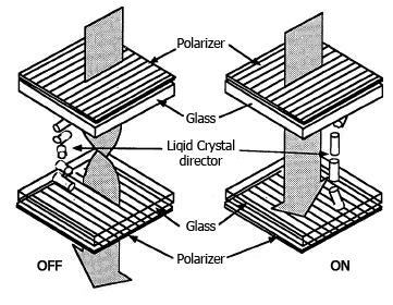
A typical LCD consists of polarizers, glass substrate with electrodes & liquid crystal fluid.
A layer of liquid crystal is sandwiched by two alignment layers, the front layer & rear layer. Each of the layers will align the liquid crystal molecules to one direction, the alignment directions of the front layer & rear layer is with an angle, so that a helical structure of liquid crystal is formed.
Next to the alignment layer is the electrode layer, the front and rear electrodes can form an electric field in order to switch the LCD on & off.
When the electric field exists, the helical structure of the liquid crystal is distorted, all the liquid crystal molecules will align to the electric field, this is an "on". When the electric field is removed, the helical structure is restored, this is an "off".
The electrodes are transparent layers made of a material called Indium tin oxide(ITO).
The electrodes are etched to patterns so that to display beautiful digits, icons & graphics.
Polarizers are attached on the outer surfaces of the glass substrates.
With a suitable arrangement of the polarizing axis of polarizers, a light switch is formed. That is the basic theory of LCD.
What type of LCD is available?
In terms of degree of twist, we have TN, HTN,STN, FSTN & FFSTN.
In terms of background color, we have Black & White, Green, Blue & Grey. Making other colors is also possible by using additional process like "ink printing" ,or special material like colored polarizer & colored backlight.
In terms of lighting condition, Lcd should be reflective for non-backlighting, and transmissive or transflective which requires backlighting.
In terms of displayed pattern, we have digits, icons, characters & graphics.
In terms of operating environment, we have normal temperature, wide temperature, extended temperature, indoor, outdoor & anti-glare.
In terms of operating voltage, we have low , normal & high voltage.
In terms of display thickness, we have 2.7mm, 1.9mm, 1.6mm & 1.3mm. (+/-0.2mm)
What is the viewing direction?
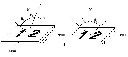
When a LCD is observed in different directions, there is one direction that the contrast is the best . This is the so called "viewing direction" or "preferred viewing direction".
The preferred viewing directions can be specified by "time". The common one is 6 o'clock, i.e.. the direction parallel to the positive Y-axis of the display. Other viewing directions are also available. It is simply making changes in manufacturing process.
What is the difference between reflective, transflective and transmissive displays?
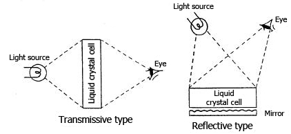
A transmmissive display will have a transmissive front polarizer & a transmissive rear polarizer,a backlight is required.
A reflective display will have a transmissive front polarizer & a reflective rear polarizer.
The reflective layer that is behind the rear polarizer can reflect the incident light so that the user can make use of the ambient light, backlight is not required.
A transflective display will have a transmissive front polarizer & a transflective rear polarizer, the transflective polarizer can let portions of the incident light pass through and reflect the rest. Therefore, transflective LCD can be operated similar to a transmmissive display when the backlight is turned on, or similar to a reflective display when the ambient light is enough.
What is the temperature compensation and why is it required?
The voltage corresponding to the LCD starting to turn on is called threshold voltage. Obtaining good contrast often require good matching between applied voltage & threshold voltage of the LCD.
The threshold voltage will change with temperature, that means at the same applied voltage, good contrast is obtained at room temperature but not the case at 75C.
In case of wide range operating temperature, for optimum contrast, adjustment of applied voltage according to temperature change is recommended. Such adjustment is generally referred as temperature compensation. It is usually done by electronics.
Why does not COG module have the Vout after initialization?
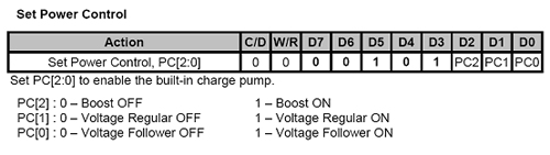
Normally, we will have a set power control command in our initialization. If you turn on the boost (Vb), the voltage regulator (Vr) and the voltage follower (Vf) in one command, the Vout may not achieve the voltage that you want.
You need to do 3 separate commands to turn on Vb, Vr and Vf and make a delay for each command. For example, you need to turn on the Vb first and delay about 5ms to make sure the booster voltage is stable. Then you can turn on the Vr and delay about another 5ms to make sure the voltage is regulated. Lastly, you can turn on the Vf.
How to make a constant current source to drive backlight?
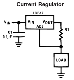
You can use LM317 to make a simple circuit for constant current driving.
You can use the following equation to calculate the current you want.
I = 1.25/R1